- Make connection as in shown in the circuit diagram for measuring armature resistance with (Ra1) and without (Ra2) brushes
- Using combination of switches in the load box inject current into the armature winding up to 110% rated value in steps of 2A
- The connection leads of voltmeter V2 are to be tapped from the surface of contact between carbon brushes and commutator, i.e. by excluding carbon brushes
- Note the readings of ammeter and voltmeters for each value of armature current
- Prevent any tendency of the armature to rotate when current flows through it
- Readings should be taken as quickly as possible to prevent the change of resistance due to heating
Note:
- Make connections as shown in the circuit diagram for field resistance measurement
- Using the rheostat vary the supply voltage in steps of 10V up to rated voltage of the field winding
- For every step of 10V, note down the readings of voltmeter and ammeter
(Megger Method)]]>
- Connect the special voltmeter as shown in circuit diagram or machine insulation resistance measurement using voltmeter method
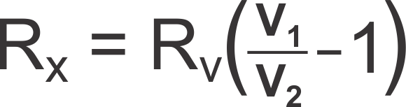
- By making contact at position no.1 as shown, note down the supply voltage, V1 in special voltmeter
- Next move the connecting lead of the voltmeter to position no.2, and note down the special voltmeter reading, V2
- Note down the internal resistance, RV, of the special voltmeter as supplied or from name plate
- Find the value of unknown resistance, RX by using
- The armature terminals (A1 and A2) are shorted together for measurement of insulation resistance between the armature winding and frame
- The field terminals (F1 and F2) are shorted together for measurement of insulation resistance between field winding and the frame
Note:
]]>
Resistance
(Voltmeter Method)]]>Machine Insulation Resistance(Voltmeter Method)
]]>(Voltmeter Method)]]>Machine Insulation Resistance(Voltmeter Method)
- Connect the Megger terminals such that the earth terminal of the megger is connected to the frame of the motor while the line terminal of the megger is connected to the winding terminal, either field or armature, depending on whose insulation resistance is being measured
- Depending on what is being measured, short either the two field terminals or the two armature terminalsusing a wire
- Rotate the Megger handle steadily at a moderate speed
- Note down the readings of armature winding to yoke and field winding to yoke insulation resistances independently
- The armature terminals (A1 and A2) are shorted together for measurement of insulation resistance between the armature winding and frame
- The field terminals (F1 and F2) are shorted together for measurement of insulation resistance between field winding and the frame
Note: